Voxel Beam
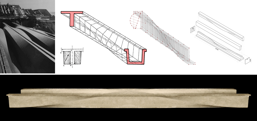
This research explored precedents in the optimization of building structures, namely the Arup beam. The Arup Beam was co-developed by John Utzon and Ove Arup for the concourse of the Sydney Opera house. Constructed from reinforced post-tensioned concrete and spanning nearly 150 ft, the beam was the result of a multidisciplinary design optimization exercise where input from both architects and engineers contributed to its final form. For a variety of aesthetic, performative and structural reasons, the beam features a varying section along its span. At the supports where bending moments are at their minimum, the beam section is U-shaped. At mid-span, where bending is at its maximum value, the section transitions into a T. This is achieved through a sine curve allowing a smooth flow of forces along the span.
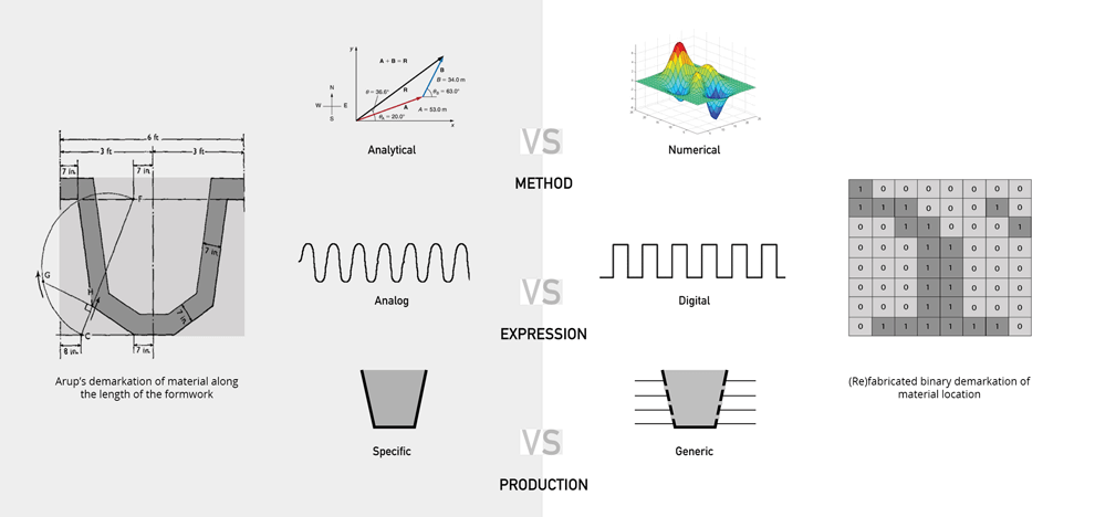
In researching the Arup Beam, the team explored three areas crucial to conceiving a contemporary version of the beam. The first dealt with the shift from analytical structural analysis techniques used in the 1950’s to more numerical methods, such as Finite Element Analysis, available today. The second thread attempted to understand the fundamental difference between an analog representation of structural forces, represented here by the Arup beam’s sinusoidal curvature, and a digital binary system of 0’s and 1’s. This aims to re-contextualize the structural beam within contemporary digital platforms. The third approach was concerned with the feasibility of fabricating results obtained from structural analysis. The team speculated that a more generic and flexible formwork could conform to various optimized geometries whilst maintaining the practicality of construction.
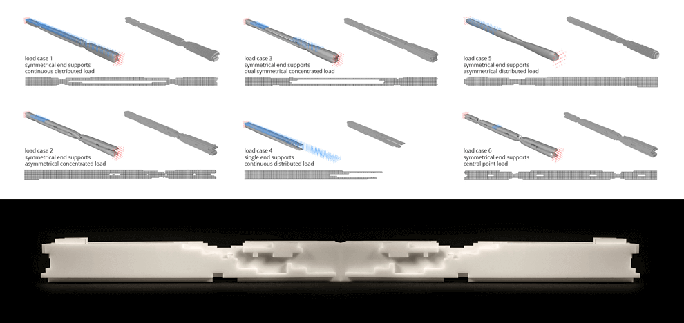
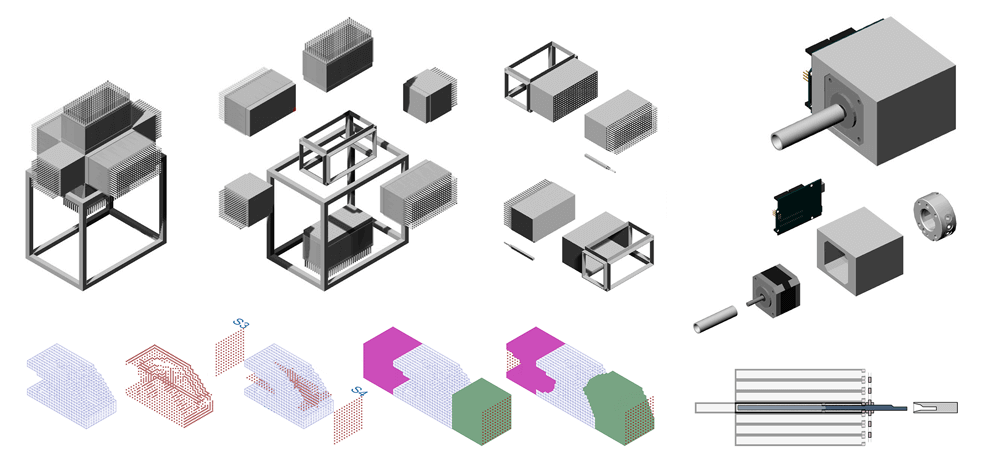
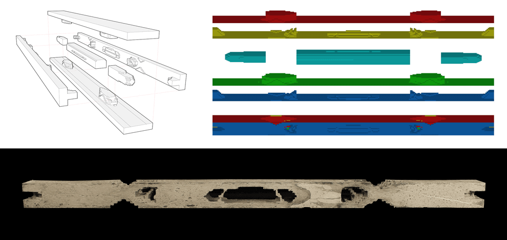
Topology optimization was explored as a means to derive a minimum compliance structure while eliminating pre-conceived notions of such structures. Its subtractive nature and wide range of application made it an ideal candidate to re-optimize the beam element. Topology optimization combines numerical analysis methods, such as the Finite Element Analysis (FEA), with optimization algorithms to describe the optimal material density distribution in a given domain with specific boundary conditions. Through interfacing Grasshopper’s parametric engine with an existing topology optimization code developed in Matlab, the authors were able to create a user friendly GUI to the complex numerical computing of densities. This allows for easy application of load and boundary conditions graphically. Grasshopper custom components were developed within the multi-paradigm programming language C#. The mold is conceived as a six sided “pin” mold. Six boxes come together to create the casting volume enclosure. Each pin comprises an aluminum hollow square extrusion with dimensions equal to those of the optimized elements. A threaded rod allows turning the pin in location and precisely locking it in place as the cast operation is under way. A robotic tool was developed simultaneously allowing a fully automated fabrication work flow.
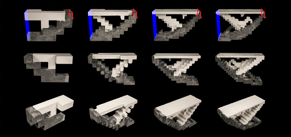
Computationally, the bounding box is exploded and its six sides are numbered and treated as reference planes. The distance from these reference planes to each voxel is calculated and aggregated per side. It is then translated into a “number of rotations” value that is passed on to the processor mounted robotic tool. The team also explored a fixed load case at different resolutions. The images show various Voxelbeam resolution tests each representing one half of a cantilevered support supporting a distributed load. Four resolutions were used ranging from 1 to 0.25 cubic inches. Plaster represents areas in tension, concrete represents areas in compression. As these models act as structural diagrams, the intent here is to illustrate the possibility of combining various materials to form one structure: one that is strong in tension and another that is strong in compression. The interface between two such materials is also crucial in understanding the behavior of such structures. This takes inspiration from hybrid materials such as steel-reinforced concrete but instead deals with these within a topology optimization framework.
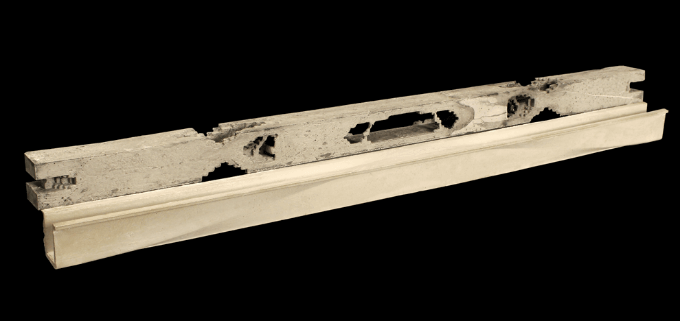
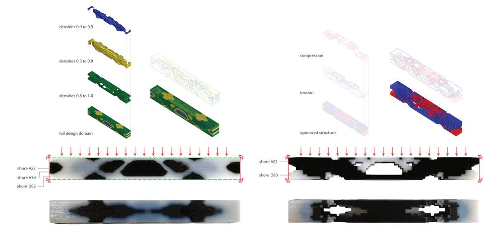
A very complex and expensive formwork was utilized to realize the geometry of the Arup Beam. The team chose to fabricate a Voxelbeam with the same proportions and load case as the original Arup Beam. 27% was obtained through a calculation of the Arup beam’s volume as a percentage of its bounding box. This ratio was used as a benchmark when running the optimization calculations. Therefore, (re)fabricated beam uses the same amount of material as the original beam, but it is distributed in a radically different way. A CNC router was used to sculpt the foam molds into shape. The final mold was a 7 piece mold describing over 90% of the actual topology optimization result. The intricate geometry of the optimized beam posed a fabrication challenge as was expected. Pouring of concrete had to happen at either end. If we think of the Arup beam as being derived not from a linear array of two dimensional cross sections, but as a three dimensional distribution of material within a given boundary, how can some of the original concepts be reinterpreted? How can they be improved? The sinusoidal curvature of the Arup beam is an aesthetic manifestation of the analysis and form finding techniques used in its design. It is an analog structure in technique and form. The Voxelbeam is a digital structure. It finds its formal inspiration in the principles of topology optimization. It preferences the intelligible over the ideal. The Voxelization of a given minimum compliance structure gives the observer an indication of the techniques used in its analysis. It also can help to rationalize production and promote formal flexibility. Both experiments are based on the same load condition: fully constrained DOFs at both ends and an evenly distributed load acting downwards. An Object Connex multi-material 3d printer was utilized for these tests. The first approach dealt with separating elements by either the tensile or compressive forces acting upon them. The durometer value i.e. hardness parameter was used as a proxy for such materials: a harder material for compressive forces and a softer more stretchy material for tensile forces. The second approach deals with the aggregation of densities and combining them to form groups where each group is then assigned a different material. Elements with densities ranging from 0.0 to 0.3 are assigned a soft material while those between 0.8 and 1.0 are assigned a relatively harder one.
